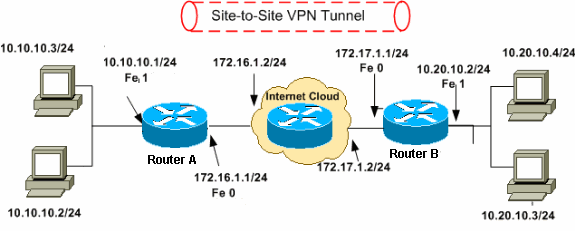
A configured router added to a session establishes a VPN tunnel to Cisco dCloud automatically when your session is active. This process is typically transparent and reliable. In situations where you are unsure if the VPN tunnel is established or for additional information when troubleshooting, use the steps on this page.
- Download Cisco VPN Client By Cisco Systems, Inc.
- Solved: Client VPN From Cisco Router To Commercial VPN ...
The Cisco secure WebVPN router login screen The Cisco SSL AnyConnect VPN client was introduced in Cisco IOS 12.4 (15)T and has been in development since then. Today, Cisco SSL AnyConnect VPN client supports all Windows platforms, Linux Redhat, Fedora, CentOS, iPhones, iPads and Android mobile phones. RV345P Dual WAN Gigabit POE VPN Router. RVL200 4-Port SSL/IPsec VPN Router. Cisco VPN Clients. VPN and Endpoint Security Clients. The VPN client is entirely dependent on the settings of the VPN router to be able to establish a connection. TheGreenBow VPN Client is a third-party VPN client application that makes it possible for a host device to configure a secure connection for site-to-site IPSec tunnel with the RV34x Series Router. These cookies are necessary for the website to function and cannot be switched off in our systems. They are usually only set in response to actions made by you which amount to a request for services, such as setting your privacy preferences, logging in or filling in forms. Learn how to configure Cisco VPN gateway and support network-to-network IPsec VPN topologies using a router as the VPN gateway with Cisco EzVPN. VPN hardware; This article explains the VPN hardware client configuration that will support a full-crypto peering relationship for Cisco's EzVPN IPsec gateway. Learn about the four configuration.
Pre-requisites
Before you can troubleshoot your VPN tunnel, ensure that you have met the follow pre-requisites:
- You added your router to a session when you scheduled the session or after the session became active.
- Your session is active.
Testing Connectivity
- Using a straight through Ethernet cable, connect the Wired Client to an available port on the router. This varies by router model; however, all routers recommended for use with Cisco dCloud have an available port.
- Configure the Ethernet port on the Wired Client to receive its IP address via DHCP.
- Confirm that the Wired Client has received an IP address.
- From the Wired Client, browse to http://dcloud.cisco.com/ to access the Cisco dCloud UI and then log in with your Cisco.com credentials.
- Use the Bandwidth Test to verify that the port needed for VPN connectivity (TCP 443) is not blocked at your site.
- From the Wired Client, ping AD1 at 198.18.133.1. This ping needs to be successful.
- From the Wired Client, Telnet to the router at 10.0.1.1. You will not be prompted to login.
- Use the following commands to verify the state of the VPN tunnel:
• show crypto isakmp sa – should show a state of QM_IDLE.
• show crypto ipsec client ezvpn – should show a state of IPSEC ACTIVE

- If the VPN tunnel is not up, issue a ping to AD1 sourced from VLAN 10.
Earlier, I wrote an article showing how to do a VTI (Virtual Tunnel Interface) from a Cisco ASA to a Fortigate Firewall. Today, I will cover a route-based VPN with a Cisco Router instead of a Cisco ASA using VTIs. Where as the ASA only supports BGP with its VTI implementation, the router is a bit more flexible and allows for OSPF.
Initially, this post was born from a customer that required some VPN connectivity via VTI on the ASA which later turned into a VTI on a Cisco Router. This was great because it gave me an opportunity to write about it. While on-site, we were testing with FortiTester and reviewing the Fortigate features. This took up some time of course, but when we tested the router-based VTI, we ran out of time. I asked the customer if I could work on the config and get back to him, they were gracious enough to allow me to do so; Thank You Mr. Customer. Here is what I did.
My Configuration
Below, we can see that I have one interface that is acting as the Internet (192.168.200.0/30) and a tunnel interface tied to both WAN ports (obviously using different methods; Cisco and Fortinet respectively). The plan is to establish an encrypted channel using the 192.168.200.0/30 network, then establishing the tunnel interface between the 192.168.170.88/30 subnet and be able to use dynamic routing (OSPF).
Cisco Router Configuration
Using a Cisco 2921 in my lab, I configured the VPN using the config I was using on-site at the customer. Here is the config:
I will break each section down below:
This is the configuration that will allow you to define the pre-shared key with the particular remote peers. In my case, it is the FortiGate’s IP address of 192.168.200.2 and the pre-shared key is fortigate
Next we will define the Phase I crypto profiles
In my example above, I am telling the router that I will present and accept Phase I connections that meet the following proposal. In my example, I require that you use AES 256 as the encryption type and SHA 256 as the hashing algorithm. Additionally, I am expecting pre-shared key as the authentication instead of a certificate. Lastly, I want to use DH group 2 (Diffie Helman).
Next we will configure the Phase II proposals
Here we are expecting and will be exchanging AES 256 with a hashing of SHA 512.
Next we will configure a profile that will reference the transform-set created previously and will be assigned to a tunnel interface.
Now we will create the VTI or Virtual Tunnel Interface
As we can see in the config snippet above, we are calling the ipsec profile we defined in the previous step as well as the IP address 192.168.170.90/30 and we are defining where the tunnel initiates from (the tunnel source of 192.168.200.1) and the destination of the tunnel (192.168.200.2).
Finally, we will configure a few test connection items such as loopback interfaces and OSPF.
This is a simple loopback interface that I will use to advertise over the VPN.
Above we can see a basic OSPF configuration
Fortigate Configuration
Things are much easier on this side of the house IMHO.
Here we are defining the IP address of the remote peer (Cisco Router) and we are telling the VPN that we are NOT using NAT Traversal. If you are not familiar with NAT T, here is a blog site that discusses it.
Next we have our Phase I proposal. This is equivalent to the crypto isakmp policy 11 from the Cisco Configuration portion. Additionally, we are defining what DH groups I want to use as well as the Key Lifetime. Even if the Key Lifetime do not match, the tunnel WILL come up, you will just have strange re-keying issues throughout the tunnel’s lifetime.
Then we have our Phase II configuration. Here we are defining the Phase II proposal. As you can see, I have multiple proposals one of which matches ROUTER-IPSEC transform-set from the Cisco Configuration portion.
BEWARE OF PFS: I tend to use it. But a majority of Phase II issues I run into, is because either the proposals do not match or PFS is either enabled or disabled when it should or should not be.
When you have finished creating the VPN, the Fortigate will automatically create a tunnel interface for you, however it will have 0.0.0.0/0 assigned to it. We will need to modify the IP address. In our case, we used the 192.168.170.88/30 network. This directly ties into the Cisco interface Tunnel1 section. We can see that much like the Cisco config, we are defining the remote IP of the tunnel.
Download Cisco VPN Client By Cisco Systems, Inc.
We will create some policies that permit or deny traffic as needed.
Since I am using Central NAT, I will create an entry telling the Fortigate NOT to NAT traffic over the VPN tunnel interface.
As you can see, the NAT is disabled.
Now for my OSPF configuration
Results
Her we can see the routes learned via OSPF from the Cisco side
And here we can see the routes learned via OSPF from the Fortigate side.
Side Note
When I was on-site and I was troubleshooting the problem, I did not see the error I was having, however when I got home and decided to reconfigure the Cisco side piece-by-piece, I noticed that I was missing a line on the tunnel interface configuration.
Here is the debug I was seeing
I was getting Phase I up between the router and the Fortigate but then it would drop. I tried all kinds of things, the piece I was missing on the Cisco side was:
Once I added that, everything was right as rain.
Hope this helps.
20191111 UPDATE: Since the customer was running IKEv2 and my example was IKEv1. Here is the update for IKEv2. I recommend IKEv2 for obvious reasons, but here you have both.
On the Cisco Router
Phase I
Here you can see we are calling for the ikev2 proposal instead of the crypto isakmp one we had in the IKEv1 version of the config.
Keyring
Again, here we have the specific ikev2 keyring to be used.
IPsec Profile
Once again, we are differentiating between IKEv1 and IKEv2 on the profile and calling the correct KEYRING
Here we are calling out the same transform set we used earlier in IKEv1

Interface
interface Tunnel1
tunnel protection ipsec profile Fortinetv2
!
Finally, we need to reference the correct profile on the tunnel interface. This will force the Tunnel1 interface to use IKEv2.
On the Fortigate
Inside the VPN configuration, under Authentication change the IKE Version from 1 to 2.
VPN Validation
Solved: Client VPN From Cisco Router To Commercial VPN ...
Here we can see the Phase I up or ready
We can see the quad 0’s up for Phase II
